Lab 6
The Internet of Things and Serial Peripheral Interface
For Lab 6, we used a WiFi development board and a temperature sensor to learn how to build a simple IoT device and implement SPI functionality.
We used a ESP8266 with onboard WiFi and an integrated antennae that was preprogrammed to host the HTTP web server with an HTML page that was generated by our MCU. The DS1722 Digital Thermometer with SPI/3-Wire Interface from Maxim Integrated supports an SPI interface and was the temperature sensor we used for readings.
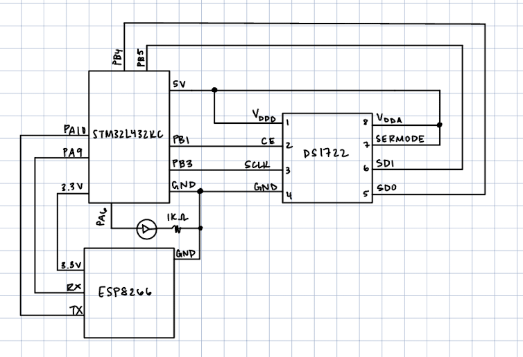
Similar to the previous MCU labs, the hardware setup for the DS1722 chip was relatively straightforward and thus, I wired this up first to make sure I could toggle the correct pins with my code. Additionally, there was already space for the ESP8266 to pop into on our E155 protoboard, which added to the ease of hardware. The schematic for the hardware is shown in the figure below.
The code was able to accurately read positive and negative temperatures as well as display values at different user-controlled resolutions, meeting both proficiency and excellence specs.
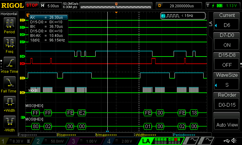
The testing and debugging for this lab was daunting at first given that it was my first time working with the logic analyzer and it felt like a steep learning curve to first learn how it worked, and then to learn efficient ways to use it to debug. For this lab, I mostly used it to confirm that SPI transactions were working or not, and reverted back to the Segger debugger for more in depth testing and debugging.
A sample SPI transaction from the analyzer is included below to prove that the information is being sent over correctly. The screenshot shows the write followed by read transaction.
This lab was a great introduction to SPI because it required us to really get to know the different functions needed and also how to debug SPI projects.
I spent a total of 20 hours on this lab.