Lab 4
Digital Audio
Lab 4 was our introduction to using our STM32 Microcontroller. We used the microcontroller to generate sqaure waves at specified frquencies by toggling a GPIO pin, which would then power a 8ohm speaker to play a song, specifically Fur Elise. I also created a array of frequency and durations to allow the speaker to play Twinkle Twinkle Little Star.
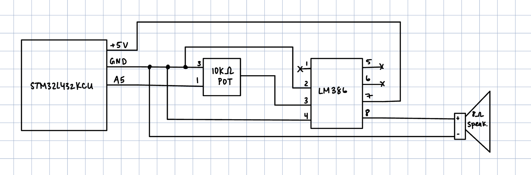
The hardware setup for this lab was relatively straightforward - I used GPIO pin A5 and to output the square waves, which then feeds into a 10Kohm digital potentiometer to control the output volume. Then, the wave will be fed into the LM386 audio amplifier and an 8-ohm speaker to play the notes. The following figure shows the schematic for this setup.
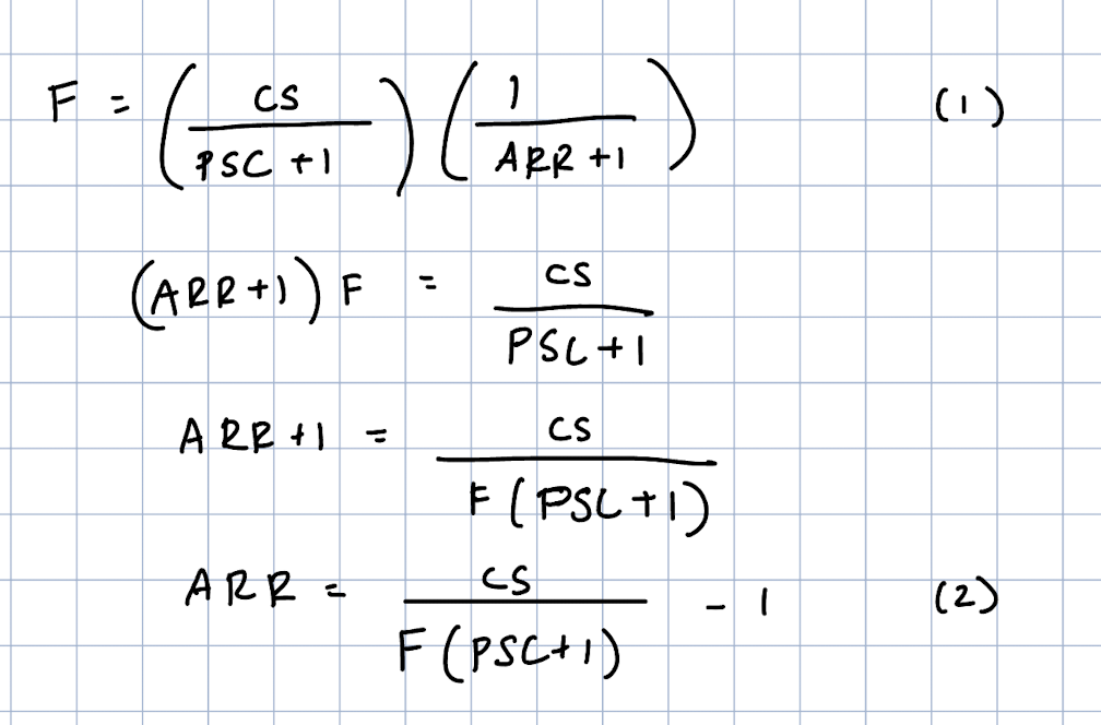
The image below shows the math used to calculate ARR for specified frequencies. I started with equation (1), which shows the frequency in terms of ARR, and rearranged it to get equation (2), which shows the ARR in terms of desired frequency (which would be inputted through our array of notes and durations).
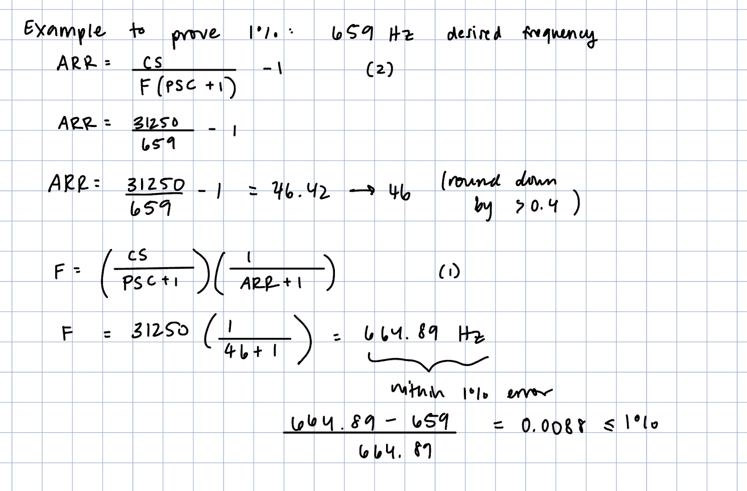
I will also include a sample calculation using an example input frequency to prove that this allows for the necessary accuracy of 1%. Let’s say we have a desired frequency of 659 Hz. Starting with equation (2) from above, we can calculate an ARR of 46.42, but this would round down to 46. This shows that this is a good example to use because we are trunctating the ARR by over 0.4.
Then, we can work backward using this calculated ARR by plugging into equation 1 to see the actual output frequency, which comes out to be 664.89Hz. We can then confirm that this is within 1% error to the actual desired frequency using the equation for scientific error.
I only used 1 timer to toggle the GPIO pin at specified square waves, and used a nop while loop for the delay function. This is what controls the duration piece of the notes, and I am using 887 nop instructions for the delay, meaning that the minimum delay/duration that is possible is 1/887 which is 1ms. The nop instruction method also allows for an unbounded maximum duration.
The figure below includes calculations for minimum and maximum frequencies using the same equation (1) from above.
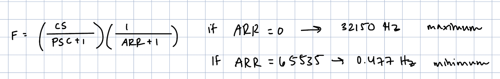
The range from 0.477Hz to 32150Hz is a sufficient range for the human ear.
The following videos show Fur Elise and my rendition of Twinkle Twinkle Little Star playing using the setup detailed above.
Overall, I thought that this lab was a great introduction to using the MCU and although there were some initial learning curves at the beginning (I did not feel very confident in my C and was out of practice), I feel a little more caught up after struggling with this lab. This was also an interesting shift from the other labs where the hardware was super straightforward and was something I could wire up first. I also felt like it was hard to do preplanning for this lab (like draw schematics or block diagrams) which was werid to me after getting into that habit from the previous few labs. Debuggina also felt like a learning curve because it had been a long time since using the Segger tools. It took me about 8 hours in total to complete.